Monday, 9 January 2012

CRO


Hi friends, this time I am going to tell about one of the most used electronic instruments named CRO. The CRo can be expanded as the Cathode Ray Oscilloscope.
The cathode-ray oscilloscope (CRO) is a common laboratory instrument that provides accurate time and amplitude measurements of voltage signals over a wide range of frequencies. Its reliability, stability, and ease of operation make it suitable as a general purpose laboratory instrument. The heart of the CRO is a cathode-ray tube. It is an electronic instrument capable of giving a visual indication of a signal waveform. It is widely used for measuring the voltage as a function of time. The CRO depends on the movement of an electron beam, which strikes a screen coated with fluorescent material, to produce a visible spot. If the electron beam is deflected on x-axis and y-axis, a two dimensional display is produced.


A general purpose CRO consists of the following main components:

1.      Cathode Ray Tube (CRT).
2.      Vertical Amplifier.
3.      Triggering Circuit.
4.      Sweep generator.
5.      Horizontal Amplifier.
6.      Delay line.
7.      Power supply.

  1. Cathode Ray Tube (CRT): The heart of the CRO is the Cathode Ray Tube which generates the electron beam, accelerates it to a high velocity and deflects it to create the image. The CRT contains the Phosphor screen where the beam becomes visible.To accomplish these tasks, various electrical signals and voltages are required which are generated by the remainder of the blocks. Before striking the screen the electron beam passes between a set of deflection plates. The vertical and horizontal movements are independent of one another so that the spot on the screen can be positioned anywhere on the screen by the simultaneous application of appropriate vertical and horizontal voltage inputs. When a periodic signal is applied to the vertical plates and a sawtooth signal of the same period is applied to the horizontal plates, the spot will trace an image of the periodic signal on the screen.

  1. Vertical Amplifier: The signal to be viewed is fed to the vertical amplifier, which is a wideband amplifier used to increase the potential of the input signal to a level that will provide a deflection of the electron beam.

  1. Triggering Circuit: To synchronize the horizontal deflection with the vertical input, such that the horizontal deflection starts at the same point of the input vertical signal, a synchronizing or triggering circuit is used. This circuit is the link between the vertical input and the horizontal time base.

  1. Time base generator (sweep generator): Time base generator is used to generate the sawtooth voltage required to deflect the beam in the horizontal direction. It controls the rate at which the beam is scanned across the face of the CRT and is adjusted from the front panel.

  1. Horizontal Amplifier: The horizontal amplifier is similar to the vertical amplifier and it increases the amplitude of the signals generated in the sweep generator to the level generated by the horizontal deflection plates of the CRT.

  1. Delay line: All electronic circuitry in the oscilloscope cause a certain amount of delay in the transmission of signal voltages to the deflection plates. Comparing the vertical and horizontal deflection circuits in the oscilloscope block diagram, we observe that signal processing in the horizontal channel involves trigger circuit, time base generator, and horizontal amplifier whose output is fed to the horizontal deflection plates. This whole process takes time. To allow the operator to observe the leading edge of the wave form, the signal drive for the vertical CRT plates must be delayed by at least the same amount of time. This is the function of the delay line.

  1. Power supply: The power supply block provides the voltages required by the CRT to generate and accelerate the electron beam as well as to supply the required operating voltages for the other circuits of the CRO. Relatively high voltages are required by CRTs for acceleration; low voltages are required for the heater of the electron gun, which emits the electrons. Supply voltages for the other circuits are various values, usually not more than a few hundred volts..


There are many applications of CRO, a few of them are:

·         Tracing of an actual waveform of current or voltage.
·         Determination of amplitude of a variable quantity.
·         Comparison of phase and frequency.
·         Measurement of capacitance and inductance.
·         In televisions.
·         In RADAR.
·         For engine pressure analysis.
·         For tracing transistor curves.

 I hope this was useful. Keep visiting the blog for latest posts….


Tuesday, 20 December 2011

Microprocessor


Hi viewers it’s been a long time to learn one more electronic device. As one reads the topic title one gets the question that what is a microprocessor? And what is its function and what is the internal structure of the microprocessor. As you all know microprocessor can be called the heart of the microcomputer system. The further information gives u the facts about processors in detail.

  As mentioned earlier listening to the word microprocessor the fact or question that comes to one’s mind is what a Microprocessor is, a microprocessor is a chip or a programmable device which accepts the input in the form of binary and processes it according to the instructions stored in the memory, and provides result as output. It is generally termed as the heart of the computer because it performs all operations and controls the system. A microprocessor based system consists of three basic parts namely: microprocessor, the memory, and the peripheral I/O devices and are interconnected by the data bus and address bus and the control bus.
The memory stores the binary instructions and the data for the microprocessors. The memory can be classified into main memory and secondary memory. Microprocessors do not perform the programs stored in secondary memory directly….. 
The input/output devices are the means which enables the processor to interact with the physical world. Some of the input devices: keyboard, scanner, A/D converters, switches, cameras, microphones, etc. Some of the output devices are: LEDs, seven-segment displays, LCD displays, printers, and monitors.

Evolution of microprocessors:-
Evolution of processors
  • The first microprocessor was introduced in 1971 by the Intel Corporation which was a 4bit microprocessor, Intel 4004. Other 4-bit microprocessors are : Intel 4040, PPS-4(by Rockwell International), T3472(by Toshiba), and so on..
  • The first 8-bit microprocessor named Intel 8008 was developed in the year 1972. the first microprocessor using NMOS technology was Intel 8080 developed in 1973. other 8-bit processors are: Intel 8085(in 1975), Zilog’s Z80(1976), and Z800, Motorola’s MC6800(1974) and MC6809, National semiconductor’s NSC800, RCA’s 1802(1976) and so on..
Intel 8008

  • The first multichip 16-bit microprocessor was National semiconductor’s IMP-16, introduced in 1973. the first 16-bit single chip microprocessor was Texas instrument’s TMS 9900. Intel’s first 16-bit microprocessors was 8086(in 1978), other 16-bit processors by Intel:80186(in 1982),80286(in 1982), other popular 16-bit processors are Motorola’s 68000(1979), 68010, and 68012;  Zilog’s  Z8000; Texas instrument’s TMS series and so on..
IMP-16

  • 32-bit processors came into existence in the 1980’s. The world’s first single-chip 32-processor was introduced was introduced by AT & T Bell Labs in the year 1980 which was named as BELMAC-32A. The first 32-bit processor by Intel was iapax 432 (in 1981). Some other 32-bit processors are: Intel 80386(in 1985), Intel 486,Pentium,Pentium pro, Pentium II, PentiumIII, and Pentium IV, AMD’s K5,K6 and K7 and Motorola’s 68020(1985) etc..
BELLMAC-32A

  • Some of the popular 64-bit processors: AMD’s AMD64(2003), Intel’s x86-64 chips etc.,.
  • Some of the recent processors by Intel are: Intel dual core, Intel core 2 solo, Intel core 2 duo, Intel core 2 Quad, Intel core 2 extreme, Intel core i3, Intel i5 and Intel i7 etc.,. For more details of latest processors of Intel click here


I


Intel i7
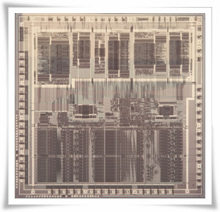
Inside a microprocessor:

The important functional blocks include ALU, the register file, and the control unit.
Internal Architecture

Arithmetic Logic Unit (ALU):
The ALU is the core component of all processors. It performs entire integer arithmetic and bitwise logical operations of the microprocessor. ALU is a combinational circuit and has two data input lines, a data output line, and a status line. It gets data from registers of the microprocessors, processes the data according to the instructions from control unit, and stores the results in its output registers. All modern ALUs use binary data in 2’s complement format.
The integer arithmetic operations performed by the ALU are addition, subtraction. Some 16-bit, 32-bit and 64-bit microprocessors also performs multiplication and division operations, in other processors multiplication and division operations are performed by writing algorithms  using addition and subtraction operations.
Some of the processors performs Logical operations like AND, OR, EXCLUSIVE OR, operations. ALU also performs bit shifting and comparison operations.
Register File: The register file comprises of various registers used primarily to store data, address, and status information during the execution of a program. Some of the commonly found registers in most of processors include: program counter, instruction register, buffer register, status register, the stack pointer, general purpose registers, and temporary registers.

·         Program counter: The PC is a register which stores the address of the next instruction to be executed and hence play a central role in the sequence of machine instructions that a processor executes.
·         Instruction register: It stores the code of the instruction currently being executed. The control unit extracts the code from the instruction register and processes it.
·         Buffer register: Buffer registers interface the microprocessor with its memory system. The two standard buffer registers are: memory address register (MAR) and the memory buffer register (MBR) . the MAR is connected to the address pins of the processor, and the MBR is connected to data pins of the processor. It stores all the data written to and read from the memory.
·         Status register: It stores the status outputs of the result of an operation and gives additional information about result of an ALU operation. The status of bits stored in the status register tells about the occurrence or non-occurrence of different conditions...
·         Stack pointer: It is a register which is used to store the address of a memory location belonging to the most recent entry in the stack. Processors use stack because it is faster to move data using PUSH and POP instructions than moving data to and from memory using a MOVE instruction.
·         General purpose registers: there is a set of registers for general purpose use, designed as general purpose registers. They are used explicitly to store data and address information. With the availability of greater number purpose registers, it would be possible to perform many ALU operations without even a need to store data in external memory..
·         Temporary registers: They are used when data have to be stored during the execution of a machine instruction.


Control unit: The control unit governs and co-ordinates the activities of different sections of the processors and I/O devices. It is responsible for controlling the cycle of fetching machine instructions from memory and executing them. It also co-ordinates the activities of input and output devices. It is the most complex of all the function blocks of microprocessor and occupies most of the chip area .
Control units are categorized into two types depending upon the way they are built. These include hard wired and micro coded control units. Hard wired controllers are sequential logic circuits, the states of which respond to the phases of the instruction execution cycle. They are very compact and fast, but are difficult to design. This is also known as RISC design. Micro coded controllers are easy to design; this is also called as CISC designs. These control units offer more flexibility than hard wired control units.

I hope this was helpful…. Do comment your opinion about this….Keep visiting !!  

Tuesday, 27 September 2011

RADAR

Radar is an object-detection system which uses electromagnetic waves—specially radio waves—to determine the range, altitude, direction, or speed of both moving and fixed objects such as aircraft, ships,spacecraft, guided missiles, motor vehicles, weather formations, and terrain. The radar dish, or antenna, transmits pulses of radio waves or microwaves which bounce off any object in their path. The object returns a tiny part of the wave's energy to a dish or antenna which is usually located at the same site as the transmitter.

The military applications of radar were developed in secret in nations across the world during World War II. The term RADAR was coined in 1940 by the U.S. Navy as an acronym for radio detection and ranging. The term radar has since entered the English and other languages as the common noun radar, losing all capitalization. In theUnited Kingdom, the technology was initially called RDF (range and direction finding), using the same initials used for radio direction finding to conceal its ranging capability..


The modern uses of radar are highly diverse, including air traffic control, radar astronomy, air-defense systems,antimissile systems; nautical radars to locate landmarks and other ships; aircraft anticollision systems; ocean-surveillance systems, outer-space surveillance ; meteorological precipitation monitoring; altimetry and flight-control systems; guided-missile target-locating systems; and ground-penetrating radar for geological observations. High tech radar systems are associated with digital signal processing and are capable of extracting objects from very high noise levels.

Other systems similar to radar have been used in other parts of the electromagnetic spectrum. One example is "lidar", which uses visible light from lasers rather than radio waves.

History
Several inventors, scientists, and engineers contributed to the development of radar.
As early as 1886, Heinrich Hertz showed that radio waves could be reflected from solid objects. In 1895 Alexander Popov, a physics instructor at the Imperial Russian Navy school in Kronstadt, developed an apparatus using a coherer tube for detecting distant lightning strikes. The next year, he added a spark-gap transmitter. During 1897, while testing this in communicating between two ships in the Baltic Sea, he took note of an interference beat caused by the passage of a third vessel. In his report, Popov wrote that this phenomenon might be used for detecting objects, but he did nothing more with this observation.

The German Christian Huelsmeyer was the first to use radio waves to detect "the presence of distant metallic objects". In 1904 he demonstrated the feasibility of detecting a ship in dense fog, but not its distance. He received Reichspatent Nr. 165546 for his detection device in April 1904, and later patent 169154 for a related amendment for also determining the distance to the ship. He also received a British patent on September 23, 1904 for the first full Radar application, which he called telemobiloscope.
In August 1917 Nikola Tesla outlined a concept for primitive radar units. He stated,  by their [standing electromagnetic waves]use we may produce at will, from a sending station, an electrical effect in any particular region of the globe; [with which] we may determine the relative position or course of a moving object, such as a vessel at sea, the distance traversed by the same, or its speed."
In 1922 A. Hoyt Taylor and Leo C. Young, researchers working with the U.S. Navy, discovered that when radio waves were broadcast at 60 MHz it was possible to determine the range and bearing of nearby ships in the Potomac River. Despite Taylor's suggestion that this method could be used in darkness and low visibility, the Navy did not immediately continue the work. Serious investigation began eight years later after the discovery that radar could be used to track airplanes.

Before the Second World War, researchers in France, Germany, Italy, Japan, the Netherlands, the Soviet Union, the United Kingdom, and the United States, independently and in great secrecy, developed technologies that led to the modern version of radar.Australia, Canada, New Zealand, and South Africa followed prewar Great Britain, and Hungary had similar developments during the war.

In 1934 the Frenchman Émile Girardeau stated he was building an obstacle-locating radio apparatus "conceived according to the principles stated by Tesla" and obtained a patent (French Patent n° 788795 in 1934) for a working system.  A part of which was installed on the Normandie liner in 1935.

During the same year, the Soviet military engineer P.K.Oschepkov, in collaboration with Leningrad Electrophysical Institute, produced an experimental apparatus, RAPID, capable of detecting an aircraft within 3 km of a receiver.The French and Soviet systems, however, had continuous-wave operation and could not give the full performance that was ultimately at the center of modern radar.

Full radar evolved as a pulsed system, and the first such elementary apparatus was demonstrated in December 1934 by the American Robert M. Page, working at the Naval Research Laboratory. The year after the US Army successfully tested a primitive surface to surface radar to aim coastal battery search lights at night.  This was followed by a pulsed system demonstrated in May 1935 by Rudolf Kühnhold and the firm GEMA in Germany and then one in June 1935 by an Air Ministry team led byRobert A. Watson Watt in Great Britain. Later, in 1943, Page greatly improved radar with themonopulse technique that was then used for many years in most radar applications.

The British were the first to fully exploit radar as a defence against aircraft attack. This was spurred on by fears that the Germans were developing death rays. The Air Ministry asked British scientists in 1934 to investigate the possibility of propagating electromagnetic energy and the likely effect. Following a study, they concluded that a death ray was impractical but that detection of aircraft appeared feasible. Robert Watson Watt's team demonstrated to his superiors the capabilities of a working prototype and then patented the device (British Patent GB593017).It served as the basis for the Chain Home network of radars to defend Great Britain. In April 1940, Popular Science showed an example of a radar unit using the Watson-Watt patent in an article on air defence, but not knowing that the U.S. Army and U.S. Navy were working on radars with the same principle, stated under the illustration, "This is not U.S. Army equipment." Also, in late 1941 Popular Mechanics had an article in which a US scientist conjured what he believed the British early warning system on the English east coast most likely looked like and was very close to what it actually was and how it worked in principle.


The war precipitated research to find better resolution, more portability, and more features for radar, including complementary navigation systems like Oboe used by the RAF's Pathfinder. The postwar years have seen the use of radar in fields as diverse as air traffic control, weather monitoring,astrometry, and road speed control.


Applications:-

Distance measurement


The information provided by radar includes the bearing and range (and therefore position) of the object from the radar scanner. It is thus used in many different fields where the need for such positioning is crucial. The first use of radar was for military purposes: to locate air, ground and sea targets. This evolved in the civilian field into applications for aircraft, ships, and roads.

In aviation, aircraft are equipped with radar devices that warn of obstacles in or approaching their path and give accurate altitude readings. The first commercial device fitted to aircraft was a 1938 Bell Lab unit on some United Air Lines aircraft. They can land in fog at airports equipped with radar-assisted ground-controlled approach(GCA) systems, in which the plane's flight is observed on radar screens while operators radio landing directions to the pilot.

Marine radars are used to measure the bearing and distance of ships to prevent collision with other ships, to navigate and to fix their position at sea when within range of shore or other fixed references such as islands, buoys, and lightships. In port or in harbour, vessel traffic service radar systems are used to monitor and regulate ship movements in busy waters. Police forces use radar guns to monitor vehicle speeds on the roads.

Meteorologists use radar to monitor precipitation. It has become the primary tool for short-term weather forecasting and to watch for severe weather such as thunderstorms, tornadoes, winter storms, precipitation types, etc. Geologists use specialised ground-penetrating radars to map the composition of the Earth's crust.


Sensors


Hi viewers,I hope that almost all of us are very familiar with the sensors because it is all most used in every day applications today just I want to make you remember about the sensors.


 Sensor is mainly defined as a device that detects certain external stimuli and responds to it in a distinctive manner. these sense condition of the process variable and produce an output
which reflects the same condition.And it can be also defined as the device which measures a physical quantity and converts it into signal which can be read by the instrument or an observer.

Uses:-
As I mentioned earlier it is used in every day objects like touch sensitivity elevator buttons (tactile sensors)
and lamps which dim or brighten by touching the base. There are infinite applications of the sensors of which most of the people are never aware, a few of them include cars, machines,
aerospace, medicine manufacturing and robotics.

The sensors may be classified as :
1. Proximity sensors
2. Pneumatic sensors
3. Light sensor

1. Proximity sensors:-
   A Proximity sensor consists of an element that changes eitherits state or an analog signal when it is close to it,but often not actually touching an object..
 Magnetic,electrical capacitanc, inductance and Eddy current methods are particlarly suited to design a proximity sensor.
Common applications for proximity sensors are:
1. Counting moving objects
2. Limiting the traverse of a mechanism.

The proximity sensors conatins three types, they are:-
  • Eddy current proximity sensors.
  • Capacitance Proximity sensors.
  • Inductive proximity sensors.
  • Eddy Current proximity sensors:-

Working principle:
When a coil is supplied with an alternating current an alternating magnetic field produce. If there is a metal object in close proximity to this attending magnetic field, the eddy currents are
induced in it. The eddy currents themselves produce a magnetic field which distorts the magnetic field responsible for their production. Consequently, the impedance of the coil changes and so
the amplitude of the alternating current. This change, at some present level, can be used to trigger a switch.

Advantages:
1. small in size.
2. Relatively inexpensive.
3. High flexibilty.
4. High sensitivity.
  •  Capacitance Proximity Sensors:-
 It consists of a simple plate with the object acting as other plate.
As the object approaches the sensor,the separation between the plate of the capacitor and object changes which becomes significant as the object is close to the sensor.
  • Inductive Proximity sensor:-

An inductive proximity sensor consists of a coil wound round core. when the end of the coil is close to a metal object its inductance changes. This  change can be monitored by its effect on resonant circuit and   the change used to trigger a switch.

It can only be used for the detection of metal objects and is best with ferrous metals

2. Pneumatic Sensors:-
Pneumatic Sensor
These sensors involve the use of compressed air, displacement or proximity of an object being transformed into a change in air pressure.
Operation:
Low pressure air is allowed to escape through a port in front of the sensor. This escaping air, in the absence of any close by object, escapes and in doing so also reduces the pressure in the near by sensor output port. However, if there is a close by object , the air cannot so readily escape and result is that the pressure increases in the sensor output port. The output pressure from the sensor thus depends on the proximity sensors.
Pneumatic sensors are used for the measurement of the displacements of fractions of millimeters in ranges which typically are about 3 to 12mm.

3. Light sensors:-
  • photo diodes
  • photo transistors
  •  photo resistors
  • Photodiodes:-
Photodiodes
Photodiodes are semiconductor junction diodes which are connected into a circuit in reverse bias, so giving a very high resistance, so that when light falls on the junction , the diode resistance drops and the current rises appreciably. these are used as a variable resistance device controlled by the light incident on it.These are used as a fastest photo detector, both for visible light and invisible light.
  • Phototransistors:- 

The phototransistors have a light sensitive collector-base P-N junction. When there is no incident light there is a very small collector-to-emitter current. When light is incident , a base current is produced that is directly proportional to the light intensity. This leads to the production of a collector current which is then a measure of the light intensity. 

  • Photoresistors:-
It has a resistance which depends upon the intensity of the light falling on it, decreasing linearly as the intensity increases. The cadmium sulphide photo resistor is most responsive to light having wavelengths shorter than about 515nm and cadmium selenide photoresistor for wavelength is less than about 700nm.
Hope you liked this post.... please comment...

Saturday, 10 September 2011

Uninterruptible Power Supply


Hello friends, I think you are all most familiar with the device UPS. Today I am going to share some information about UPS...

UPS i.e. Uninterruptible Power supply is an electrical device which supplies the power to the load when there is sudden fail in the mains.
Now a days most of the instruments or appliances are operated from ac mains & if there is a sudden failure in the ac mains then it may cause the improper functioning of the instruments. Since most of the modern systems use microprocessors, computers and hardware including semiconductor devices any interruption in the power supply may lead to uncompleted work and may make the system ineffective to use, in order to avoid these problems an UPS can be used.


According to me one who uses UPS should have to know the working of it.      The above diagram shows basic diagram of an UPS which consists of two power sources and a switch.
The two power sources can be named as primary power source and another one is secondary source. Usually AC mains are used as primary power source and battery as a secondary source. (It may be different according to the type of UPS)  The secondary source is used when the primary source is interrupted. And the switch is used as a controlling device. It changes from primary source to secondary when it detects failure in the primary source. It automatically switches from the secondary power to the primary when it is detected that primary source has returned to its normal. The power available from mains is ac and all batteries provide dc hence, in UPS there is a circuitry to convert ac to dc for battery charging called as converters. Similarly there is a device converting dc power from battery to ac power as required by the load called as inverter.


Based on the mode of operation UPS can be classified into two types. They are:-
1.      ON-LINE UPS
2.      OFF-LINE UPS

1.      ON line UPS:-


ON-line UPS

The online UPS is also called as true UPS; there are two power sources and a transfer switch that selects between them. The main feature of this UPS is that it uses the battery as Primary source and the load is connected to the inverter. The UPS converts the 230V input AC mains supply to DC power which is then used to charge the battery. The dc output of the battery is then converted into ac by using an inverter. As this regenerates the complete ac power, it will be free from any mains borne interference such as spikes and voltage variations. Online UPS can withstand large fluctuations on the main voltage. Upon the mains failure, the battery continues to drive the inverter without any break. Online UPS also has various failsafe and self diagnostic features that will instantly transfer the load onto the mains power if there is a power failure in UPS hardware or UPS is overloaded. This is done with the help of transfer switch.

There are a few advantages of On-line UPS, and a few of them can be given as:
  • This provides Failsafe/overload protection.
  • This is a true No-Break power supply.
  • This is mainly used for large servers

 This contains a very few disadvantages, and are:
  • Size and cost of ON-Line UPS is more then other types of UPS.
  • The power dissipation is very high due to conversion from ac-dc-ac.
  • Since the heat generated is very high hence it reduces the life of the battery.

 Applications:
·         Telecommunication systems.
·         Voice mail and Email systems.
·         Network servers.
·         Electronic equipments.
·         Test and diagnostic equipments.


2.      OFF-LINE UPS/ Standby UPS:

OFF-line UPS

OFF line UPS is also called as the standby UPS. In this, the primary source is the mains power and the secondary power source is the battery. In this UPS, the battery and inverter are normally not supplying power to the load. The battery charger is using the line power to charge the battery but battery and inverter are waiting in standby mode till they r needed.
Hence the name standby UPS. As main line is primary source, it is also called as line preferred UPS. The spike protector and filter are used to filter the line noise and surges and to protect the loads from severe mains conditions. When the ac mains power goes out, the transfer switch detects it and automatically switches from primary to secondary. Thus battery starts supplying the load through inverter.

Some of the merits are:
  • Low cost.
  • Silent operation.
  • Efficient.

          Demerits are:
  • Minimal power protection-not suitable for places where voltage fluctuation is severe.
  • Poor output voltage regulation.
  • Break-transfer to battery mode because of switch over delay.
  • UPS will drop the load if there is overload current and or inverter failure.

 Applications:
  • Workstations and peripherals.
  • Modems
  • Office and home PC’s
  • Business centers


  Hoping that this helped you…. Please comment….